3.3, 5, 12V Voltage Supply PCB
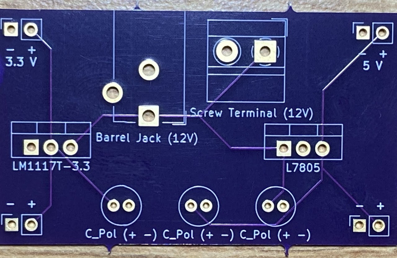
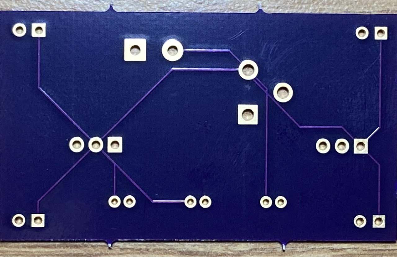
In my Electronics & Controls class (junior year) I learned how to design PCBs (printed circuit boards) using the KiCAD software. The PCB I have pictured above takes an input of 12V from a barrel jack and then runs that power directly to a screw terminal to give a 12V output to power a DC motor and also runs the power through two voltage regulators to two series of pins - one that outputs 3.3V and one that outputs 5V. The pins are interfaceable with a breadboard's power rails so that one of the power rails can have a constant 3.3V and the other can have a constant 5V.
The other cool thing about this PCB design is that it has two layers - the top layer (on the left in the image above) is all of the "charged" wiring and the bottom layer (on the right in the image above) is all of the ground wiring.
Designing a PCB on KiCAD consists of several steps. The first is to make an electrical schematic as shown below:
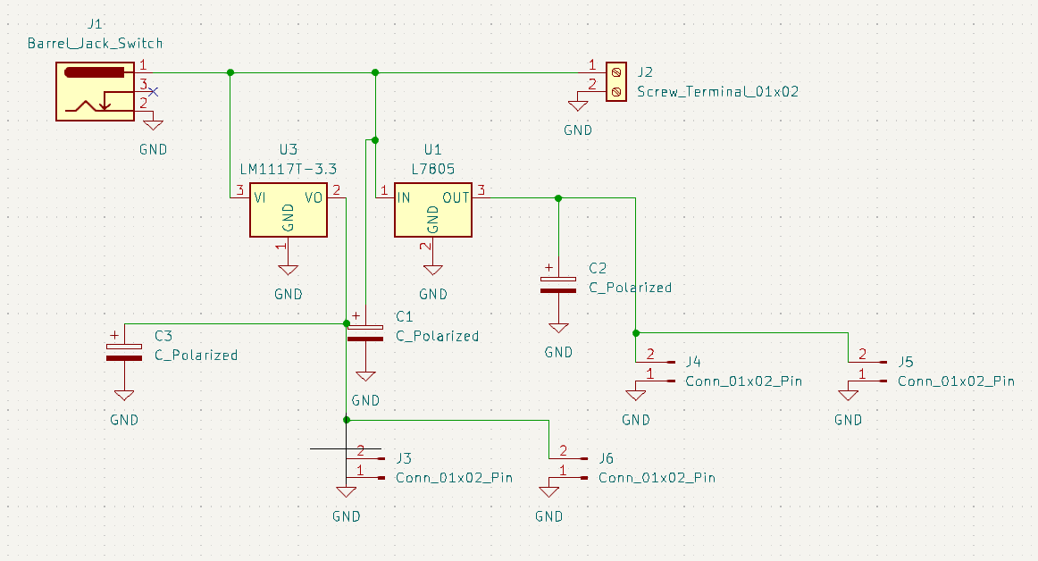
The second is to assign footprints to each element in the schematic and to actually layout the PCB:
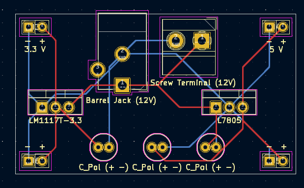
The final step is to have someone fabricate the PCB or make it yourself (I outsourced for this project) and then solder all of the electrical elements onto the PCB (the images at the top of the page do not show the electrical elements attached).